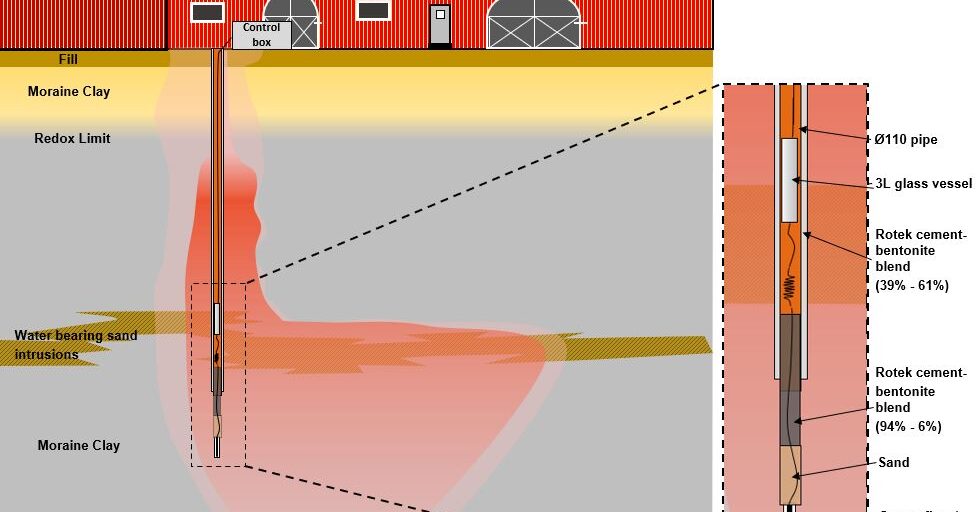
The method and equipment for deep soil water sampling have been developed to enable the collection of soil water samples for the analysis of volatile compounds, to collect samples from low-yield deposits, and to collect soil water samples from greater depths (>5 meters below ground level). The method can also be used for non-volatile compounds, such as PFAS, pesticides etc., but for these, we recommend the DualTube method. When sampling soil water for the analysis of volatile compounds, the soil water is passed through a Sorbicell before being directed into the collection bottle. The use of Sorbicells means that the flow must not exceed approximately 200 ml/day, as this could otherwise cause breakthrough in the Sorbicell. This is ensured via a specially designed control unit. The control unit maintains the applied vacuum at a level that ensures the intended flow.
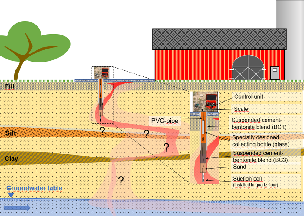
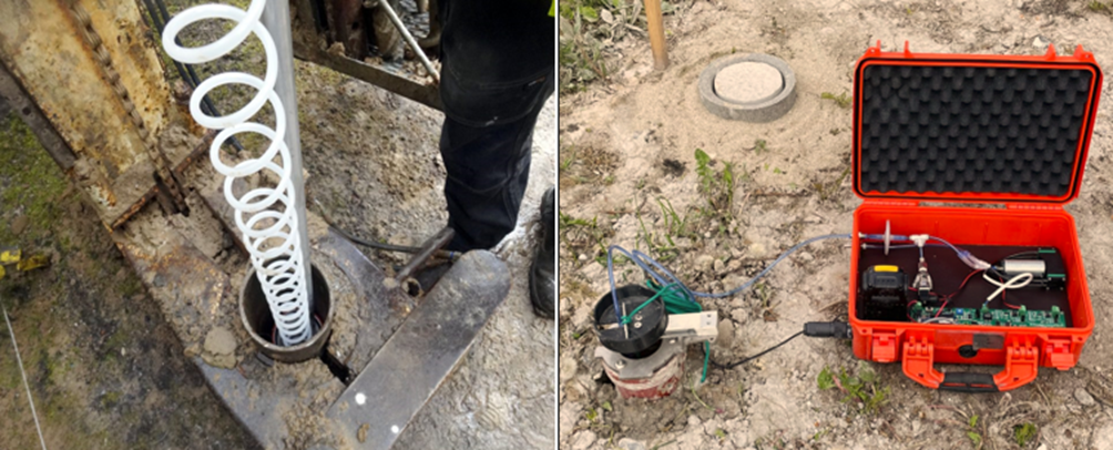
The installation hole for installation of the suction cell is made as a lined borehole using a drilling rig with a 6” auger. The bottom approximately 20 cm is made with a 4” auger to minimize the amount of suspended quartz flour in which the suction cell is to be installed. As seen above, the sampling is controlled from an automated control unit, which runs on battery and continuously sends data to DMR Cloud, allowing sampling to be monitored online from the office, while also enabling adjustments to the sampling settings (e.g., changing flow, targeted collected soil water volume, etc.). In the original method, as shown in the above figure, a specially designed collection bottle is lowered into a casing. This is done to minimize the lifting height for the soil water from the suction cell and thereby maintain as much vacuum as possible for soil water sampling.
The DualTube-method (non-volatile components):
DMR has recently developed a new method for installing suction cells for soil water sampling from depths greater than 5 meters below ground level. The method makes it easier and cheaper to install suction cells for deep soil water sampling. The suction cell can be installed using a conventional drilling rig with a 4” auger, but the method is also designed to be used with Direct Push installation, making the installation much more efficient compared to using a conventional drilling rig. The suction cell is installed at the desired depth and connected with a specially designed double tube, which is then connected to a collection bottle placed above ground. The collection bottle is connected via the specially designed lid to the automated control unit. The sampling process then begins.
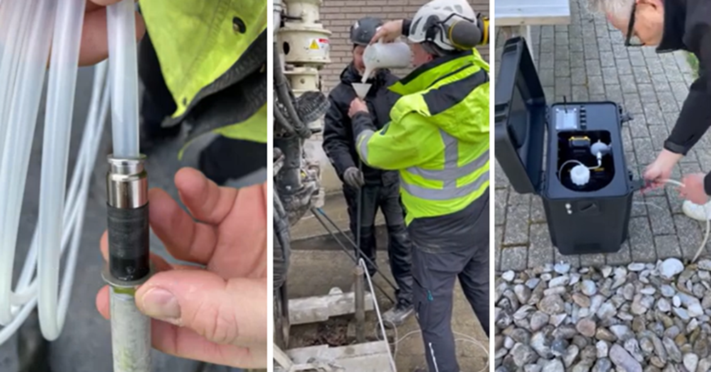
Video of installation and initiation of sampling using the DualTube-method:
DMR offers comprehensive services in soil water sampling, including consulting, installation of suction cells, and equipment sales. You can check out our equipment sales here: https://www.dmr.eu/shop/soil-water-sampling/
Do you have any questions about our equipment or technologies? Please contact one of our specialists: